Hardware
The board is a Waveshare ESP32-S3-Zero (ESP32-S3FH4R2, 4 MB flash, 2 MB PSRAM, BLE 5.0). The full parts list, the design decisions and the build phases are in SPEC.md.
Parts
| Part | Role |
|---|---|
| Waveshare ESP32-S3-Zero | MCU, BLE, USB-C |
| VS1838B IR receiver module | IR receiver (38 kHz) |
| 100 Ω resistor, 100 nF capacitor | supply filter for the IR receiver |
| TSAL-6200 IR LED, 2N2222 transistor, 330 Ω, 33 Ω and 10 kΩ resistors | IR blaster (optional) |
| SS14 Schottky diode, 2× 100 kΩ resistors, 100 nF capacitor | battery input and voltage sense (optional) |
Pins
| Signal | GPIO |
|---|---|
| IR receiver output | GPIO 1 |
| IR blaster (transistor base, via 330 Ω) | GPIO 2 |
| Battery voltage sense (optional) | GPIO 4 |
| Status LED | onboard WS2812 (GPIO 21) |
| USB control link | the USB-C port (built-in USB-Serial-JTAG) |
Schematic
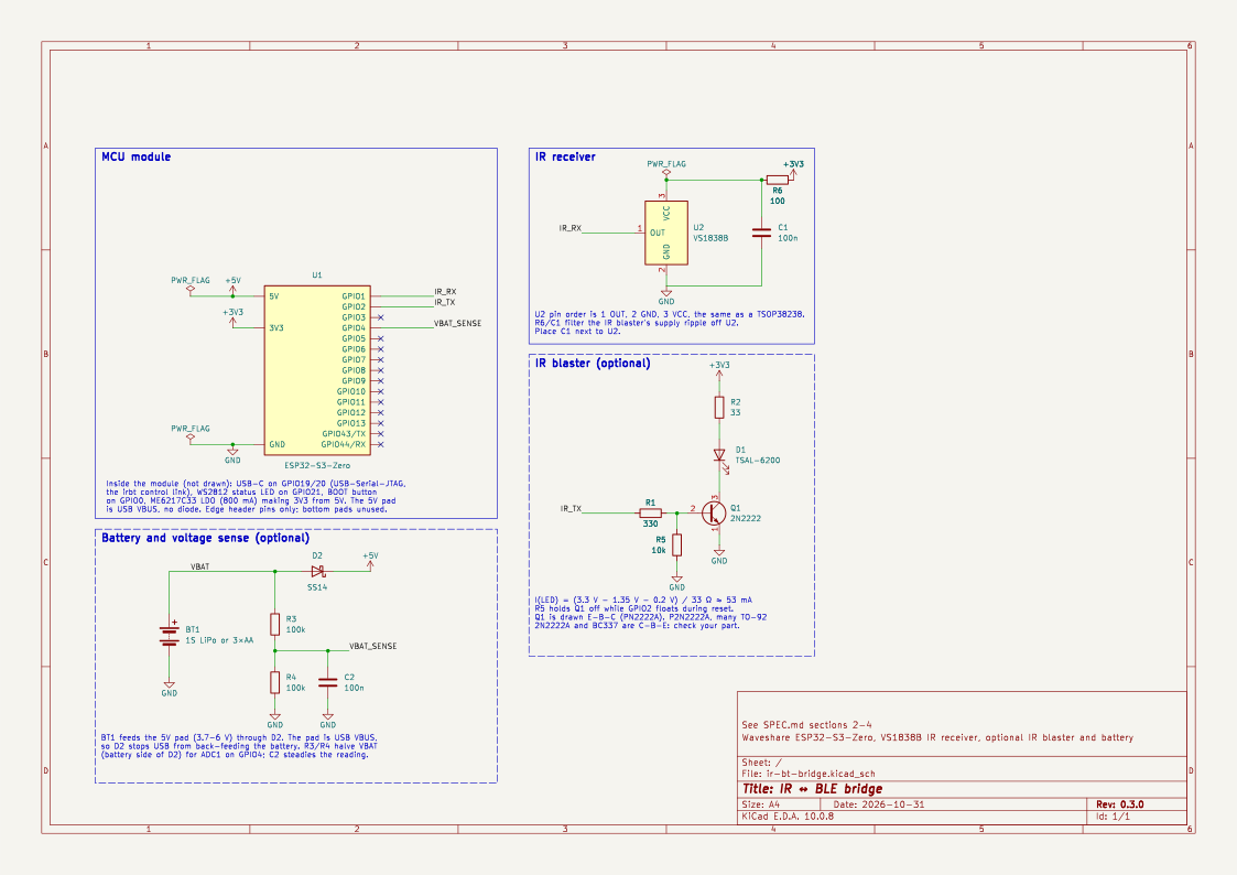
The KiCad project is in
hardware/.
It is a schematic only: the parts have no footprints, and the ESP32-S3-Zero
symbol shows only the edge header pins. The dashed boxes are the optional
parts.
Wiring
The VS1838B’s pin order is OUT, GND, VCC, the same as a TSOP38238.
VS1838B pin 1 (OUT) → GPIO 1
VS1838B pin 2 (GND) → GND
VS1838B pin 3 (VCC) ──[100Ω]── 3.3V
100nF from VCC (after the 100Ω) to GND, close to the module
The 100 Ω and 100 nF filter the receiver’s supply. The IR blaster draws ~53 mA bursts at 38 kHz from the same 3.3 V rail, and that ripple would otherwise reach the receiver’s sensitive amplifier.
The optional IR blaster:
3.3V ──[33Ω]── TSAL-6200 anode (long leg)
               TSAL-6200 cathode (short leg)
                    │
               2N2222 collector
               2N2222 emitter ── GND
               2N2222 base ──[330Ω]── GPIO 2
               2N2222 base ──[10kΩ]── GND
The 10 kΩ keeps the LED off while GPIO 2 floats during reset. The transistor is drawn E-B-C (PN2222A), but the TO-92 pinout depends on the vendor: the P2N2222A, many 2N2222A and the BC337 are C-B-E. Check the datasheet of the part you have.
The optional battery:
battery + ──[SS14, anode → cathode]── "5V" pad
battery + ──[100kΩ]──┬──[100kΩ]── GND
                      ├──[100nF]── GND
                   GPIO 4
battery − ── GND
The module’s “5V” pad is wired straight to USB VBUS, with no diode. Without the Schottky, plugging in USB with a battery attached pushes 5 V into the cells, and the battery feeds the host’s USB port. The divider taps the battery side of the diode, so it reads the battery and not USB. The diode drops about 0.3 V, so use 3×AA, or expect the 3.3 V rail to sag once a LiPo falls below about 3.8 V.
The firmware’s battery-monitor feature (on by default) reads the divider
once a minute and reports the charge to the TV as the Bluetooth battery
level. It assumes 3×AA cells; for a LiPo, set CELL to LIPO_1S in
firmware/src/battery.rs. Without a battery it reports 100%.
Status LED
The onboard RGB LED shows the Bluetooth state:
| LED | Meaning |
|---|---|
| Blue, blinking (2×/s) | No Bluetooth host connected; advertising |
| Green, steady (dim) | Connected and paired to a host |
| Purple flash | A key was sent to the host |
Keys pressed while the LED is blinking blue are dropped (no flash).